


Point Load Drawings

Utilize ISAT's Point Load Drawing Services
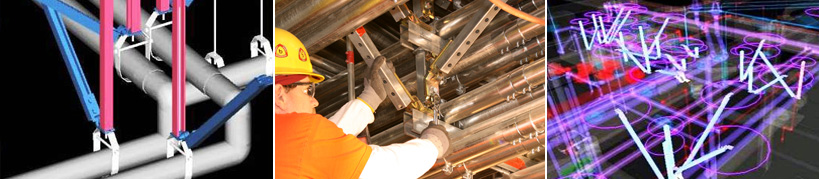
While working with your team on modeling and coordination services, it often becomes beneficial to show the brace arms. With the sophistication of our modeling, we can also show the halo at the top of the brace arm. The halo represents the anchor space from which all adjacent anchors are required to remain clear. The halo – or sphere of influence – is necessary in many projects, particularly OSHPD jobs, to maintain anchor validity.
Point load diagrams are becoming a standard requirement across the country from engineering firms. The drawing shows every connection with the suspended utilities in the building occurs. The legend further defines the type of utility and the load of the suspended utility at that point of connection.
How It WorksIt is critical to understand that no post-installed anchors are accepted by the IBC for post-tension slabs without x-raying the deck. Sleeve anchors are no longer approved for any application except masonry.
This means that anchors should be placed before the concrete slabs are poured. However, the only way to properly place these positions is to model them as part of the coordinated MEP systems.
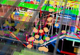
The result is a drawing littered with multi-colored dots. The point load drawing is a map of the connections and loading conditions. The documents can be presented to the structural engineer so he/she can verify that the decks are not overloaded.
Are you ready to incorporate these cutting-edge services in your next project? Contact us to learn more about our BIM Services Team and how we can help you on your projects.
Other 3D BIM and CAD Services
Watch a Short ISAT BIM Service Introduction Video

Call 877-523-6060 or contact us today to learn more
Questions? We Have Answers